




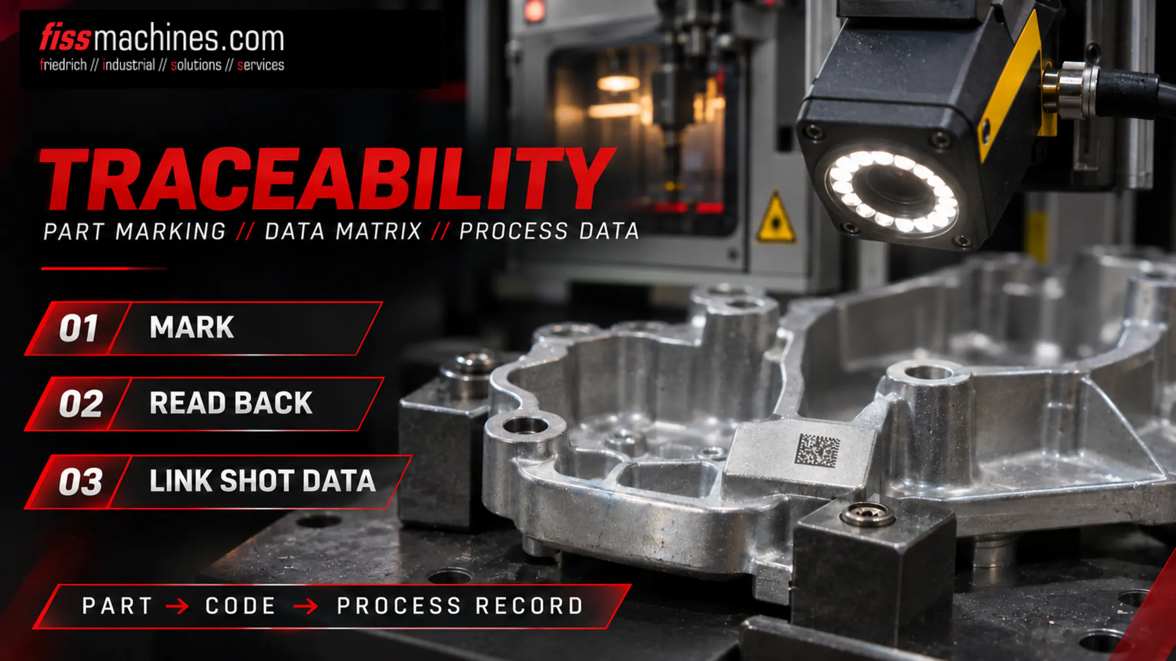
Traceability in Die Casting: Part Marking, Data Matrix Codes and Process Data
A housing leaks in the field months after delivery. Whether the foundry can name the affected shots, the melt and the die condition – or has to block weeks of production – depends on how traceability was set up in the cell.
What Does Traceability in Die Casting Mean?
Traceability in die casting is the ability to assign each casting, or at least each batch, to the conditions that produced it: shot data, melt, die and cavity, date and shift, and later inspection results. The link is a mark on the part and a database that stores the data under that identifier.
Simple parts may need only a date stamp; safety-relevant or leak-tight parts often need a code per casting.
Batch, Shift or Single Part: Which Traceability Level Is Needed?
The traceability level decides how many parts are affected by a deviation: with batch-level traceability, the whole period is blocked; with part-level traceability, the affected shots can be isolated. A review paper by the laser marking supplier Laserax notes that high-integrity castings typically require identification of 100 % of the parts produced.
Cast-In Marking
Date stamp, cavity number or alloy formed by the die. Identifies day, shift or cavity – never the individual shot.
Batch Label
Container or lot label linking parts to an order, melt or heat treatment load. Lost once parts are mixed.
Individual Code
Serial number and Data Matrix code per casting, marked in the cell and linked to its own shot record.
Which Marking Method Survives Shot Blasting, Machining and Heat Treatment?
A mark is only useful if it is readable at the end of the process chain. Castings leave the die hot, uneven and covered with release agent residue, and are then trimmed, heat treated, blasted, machined, washed or coated.
| Method | Information | Strengths | Limitations |
|---|---|---|---|
| Date stamp insert in the die | Month, year, shift, cavity | Formed with the casting; no extra cycle time or consumables | Not individual; inserts must be set and maintained |
| Laser marking | Serial number, Data Matrix, text | Fast, contactless, works on hot and uneven surfaces | Surface marks erased by blasting; deep marks take longer |
| Dot peen (pin stamping) | Data Matrix (dot type), text | Deep, permanent indentation | Slower, needs close contact and precise part position |
| Label or inkjet | Barcode, text, colour | Low investment | Removed by machining, blasting or washing |
Shot blasting is the critical step for laser marking castings. In Laserax trials, standard laser marks were largely erased; “deep marking” – removing material first and blackening the bottom of each cell – kept codes readable. On an aluminium part, 0.4 mm cells were unreadable after blasting, while 0.6 and 0.8 mm cells gave very good results (manufacturer study). Marks must therefore be qualified with real parts. Blasting itself is explained in Vibratory Finishing or Shot Blasting?
Data Matrix ECC 200: Standard and Code Quality
The Data Matrix code is defined in ISO/IEC 16022, current edition 2024. According to the GS1 DataMatrix Guideline, ECC 200 is the only Data Matrix version with Reed-Solomon error correction, which reconstructs data from a partly damaged code, and a quiet zone of at least one module is required around the symbol. Larger cells are more robust but increase code size and marking time.
Reading a code is not the same as verifying it. ISO/IEC 15415 grades print quality from 4 (best) to 0; for direct part marks, GS1 notes that this method is not sufficient. The AIM DPM guideline became ISO/IEC TR 29158; the current ISO/IEC 29158:2025 adapts the ISO/IEC 15415 method with alternative illumination and adjusted grading and reports a DPM grade.
- Agree code content, cell size and minimum grade with the customer
- Verify grades after the last process step, not only after marking
- Report illumination and method together with the grade
- Track grades over time – a falling trend shows drift
When to Mark: The Marking Station in the Die Casting Cell
The earlier the code is applied, the fewer parts can be mixed up. The marking station is therefore usually placed directly after extraction, before quenching or trimming, while shot counter and part are still in step.
Shot and Extraction
The control assigns a shot number; the robot removes the casting and checks it is complete.
Marking
The robot holds the part in front of the laser. Laserax states a focus window of about ±3 mm for a 2D head; more variation needs a 3D head with distance sensors (manufacturer statement).
Read-Back
A camera reads the code and compares it with the intended content. A part without a readable code counts as unidentified.
Trimming and Sorting
The shot record is stored under the code; the sorting gate acts on the shot status.
Fibre lasers for metal marking are high-power lasers that Laserax integrates in a Class 1 enclosure; a rotary table lets marking run in parallel with other robot movements. How stations, conveyors and sorting gates connect is covered in Automation in the Die Casting Cell.
Which Process Data Is Linked to the Part ID?
Part traceability pays off only when the right data is stored under the code. The core is the shot record; how to read shot data is explained in Understanding Shot Curves.
| Data Source | Typical Content | Link Key |
|---|---|---|
| Die casting machine | Fast-shot velocity, intensification, final plunger position, cycle time | Shot number |
| Melt and dosing | Furnace, alloy lot, melt temperature, melt treatment | Time window or batch |
| Die and temperature control | Die number, cavity, die shot count, circuit temperatures | Die set-up record |
| Inspection | X-ray, leak test, dimensional and visual checks | Part code |
| Downstream steps | Heat treatment load, machining, coating | Part code or load list |
Test stations add results under the part code, for example from X-ray and CT inspection or leak testing. Defects can then be correlated with process windows.
Rejection Logic
Shots outside the tolerance band and start-up shots after a die change can be flagged and diverted automatically. Define beforehand which deviation means scrap, which means extra inspection, and who may release a blocked part. An unreadable code is treated like a faulty shot.
Integrating Older and Used Die Casting Machines
Many cells run machines built before part-level traceability was common. Integration starts with simple signals: shot counter, good/bad signal, die open/closed. Older controls may offer shot data only through a proprietary interface or not at all; retrofitted sensors with separate data acquisition are then an option.
An OPC Foundation working group with VDMA and CEMAFON is developing OPC UA companion specifications for high pressure die casting cells, intended to replace current interfaces such as DISPO. Machine identification, status and alarms come first; process data and job management are planned. Whether a control upgrade pays off is discussed in Overhaul or Retrofit?
- Which shot values does the control record, and can they be exported per shot?
- Is there a reliable shot counter for the marking station?
- Which interfaces exist: digital I/O, fieldbus, proprietary protocol, OPC UA?
- Can missing sensors be retrofitted on the shot cylinder?
- Who keeps the database, and for how long?
Defining Traceability Requirements With the Customer
In automotive supply, IATF 16949 and customer-specific requirements frame identification and traceability; depth, data and retention time are agreed per part number. Illustrative example: a leak-tight housing may need a Data Matrix code in an unmachined area, a minimum DPM grade after blasting, shot and leak test data per code, and a cast-in marking as fallback – settled before the cell is specified.
Traceability Is Designed Into the Cell
Traceability in die casting needs a mark that survives the process chain, a code quality verified after the last step, and a data link between shot, melt, die and inspection. Date stamps remain a robust fallback; laser-marked Data Matrix codes enable part-level traceability. On older machines, the available signals decide the integration effort.
Questions About Traceability in Die Casting
Is a Cast-In Date Stamp Enough for Traceability?
A date stamp identifies the production period and, with cavity numbers, the cavity. It is enough when the customer accepts batch-level traceability; individual shot data needs a code per part.
Can a Laser-Marked Data Matrix Code Survive Shot Blasting?
Standard surface marks are often erased by blasting. Deeper marks with suitable cell sizes can remain readable, as supplier trials show. The result must be qualified with real parts and the actual blasting process.
What Is the Difference Between Reading and Verifying a Code?
A reader only checks whether the code decodes. A verifier grades its quality by a defined method, such as ISO/IEC 15415 or ISO/IEC 29158 for direct part marks, and shows decline before codes fail.
Can an Older Die Casting Machine Be Integrated?
Usually yes, but the effort varies. A shot counter and a good/bad signal are often available; full shot data may need a control retrofit or additional sensors.
Die Casting Machines and Reconditioning from FISS.
FISS supplies and reconditions used die casting machines. Contact us to discuss the machine, its control and the interfaces your cell needs.
Sources
ISO/IEC 16022:2024 – Information technology – Automatic identification and data capture techniques – Data Matrix bar code symbology specification, third edition (catalogue entry).
ISO/IEC 29158:2025 – Automatic identification and data capture techniques – Bar code symbol quality test specification – Direct part mark (DPM), edition 2.0, IEC Webstore, accessed 19 November 2026.
GS1: GS1 DataMatrix Guideline, Release 2.5.1, January 2018, accessed 19 November 2026.
A. Fraser et al. (Laserax): Review of technologies for identification of die casting parts, NADCA congress paper, 2016, accessed 19 November 2026.
A. Fraser et al. (Laserax, Mercury Marine): Important considerations for laser marking an identifier on die casting parts, technical paper, accessed 19 November 2026.
OPC Foundation: Joint working group OPC UA for High Pressure Die Casting (with CEMAFON and VDMA), working group page, accessed 19 November 2026.
